Raspberry Pi RubyでAtd7410の測定値をグラフ表示する
構成
1.Webフレームワーク sinatra
2.データベース sqlite3
動作
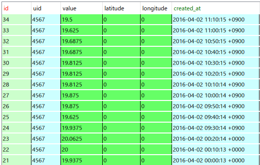
1.ATD7410で測定した温度をhttp postにてサーバーへ通知します。
通知情報 uid:識別コード latitude:緯度(予約) longitude:経度(予約) value:測定値 created_at:測定時間
測定値は10分間隔で通知します。
2.postされた情報はsqlite3に書き込みます。

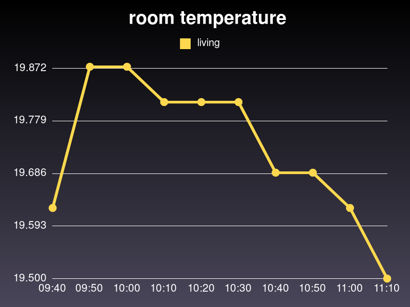
3.ブラウザーからraspberry pi をアクセスるとグラフが表示されます。
gruff gemを使用しました。

ディレクトリ構成
tsv/
+- main.rb sinatra
post.rb 温度測定 & post
tsv.db データベース
rasp_i2c.so
views
+- index.erb
layout.erb
public
+-img
+-temp.png グラフ画像
main.rb
#! ruby
# -*- coding:utf-8 -*-

require 'sinatra/base'
require 'logger'
require	'gruff'
require 'json'
require 'pp'
require 'kconv'
require 'sqlite3'

$db_file  = File.dirname(File.expand_path(__FILE__)) + "/tsv.db"
log_file = File.dirname(File.expand_path(__FILE__)) + "/post.log"
$log = Logger.new(log_file)
$log.level= Logger::INFO


#
# DB access Class
#
class Cdb
	def initialize(db_file)
	  begin
		@dbh = SQLite3::Database.new(db_file)
	  rescue => ex
		puts "class: #{ex.to_s}"
	  end
	end

	def connect
	  err_times=0
	  begin
		yield @dbh					# yield(@dbh)

	  rescue SQLite3::BusyException => ex
		puts "sql error #{ex.to_s}"
       	if err_times < 3
		  err_times +=1
		  sleep(2)
		  retry
		else
       	  @dbh.rollback
		end
	  rescue => ex
		puts "sql error #{ex.to_s}"
	  ensure
		@dbh.close
	  end
	end
end


def	create_table()
sql =<<SQL
	create table temperature (
			   id  integer primary key autoincrement,
			  uid  text	NOT NULL,
			value  real,
		 latitude  real,
	    longitude  real,
	   created_at  text );
SQL

	db =Cdb.new($db_file)

	db.connect do |dbh|
	  dbh.execute("drop table if exists temperature;")
	  dbh.execute(sql)
	end
end

# -- temperatuer  table create --
# create_table()
# exit

def take_tempe()

	res = []
	db =Cdb.new($db_file)

	db.connect do |dbh|
	  res = dbh.execute("select * from(select * from temperature order by created_at desc limit 10) order by created_at asc;")
	end
	val=[]
	tim=[]
	res.each do |arry|
		val << arry[2]
		tim << arry[5]
	end

	p	val
	h_tim= Hash[tim.map.with_index{ |daytime, i| [i, daytime.scan(/\d+:\d+/)[0]] }]
	p h_tim

	g = Gruff::Line.new
	g.title= " room temperature"

	g.data("living", val)
	g.labels = h_tim

	g.write("public/img/temp.png")
end

class MainApp < Sinatra::Base

	# 本番環境 :production  開発環境 :development localhostからのアクセスのみ許可
	set :environment, :production


	get	'/' do
#		graph("== TEMPERATUR ==")
		@graph_image="img/temp.png"
#		erb :index
		take_tempe()
		erb :index
	end


	post '/temp' do
#		pp	params

		db =Cdb.new($db_file)
		sql = "insert into temperature values (?,?,?,?,?,?);"	# id:auto increment
		db.connect do |dbh|
	  	  dbh.execute(sql,nil,params[:uid],params[:value],params[:latitude],params[:longitude],params[:created_at])
		end
		"OK"
	end

end

MainApp.run! :port => 80
post.rb
#! ruby
#
require 'net/http'
require 'url'

require  './rasp_i2c'


class Atd7410  < RaspI2c
    CONF_REG=0x03

	attr_reader :temp

	def initialize(addr, bit)
		@bit = bit
		@temp = 0
		super(addr)		# class RaspI2c の initialize を実行
		if @bit == 16
			write_reg_b(CONF_REG, 0x80)		# 16bit mode
		end
	end

	def read
		@temp = read_w(0x00)
		if @bit == 16
			@temp -= 65536 if @temp >= 65536
			@temp /= 128.0
		else
			@temp >>= 3
			@temp -= 8192 if @temp >= 4096
			@temp /= 16.0
		end
		puts "温度:%3.4f"%@temp
		return @temp
	end

end


def server_post(uid,latitude,longitude,value,created_at)

    uri="http://localhost/temp"

    res=Net::HTTP.post_form(URI.parse(uri),
        {uid:uid,latitude:latitude,longitude:longitude,value:value,created_at:created_at})
    puts    res.body
end


def main
	atd= Atd7410.new(0x48, 13)	# address   13bit
	uid = "4567"
	while true
p		ondo = atd.read
		server_post(uid, 0 ,0 , ondo, Time.now)
 		sleep 600
	end
end

	main
layout.erb
<!DOCTYPE html>
<html lang="ja">
<head>
	<meta charset="utf-8">
	<title> ONDO </title>
	<script type="text/javascript" src="js/js-class.js"></script>
	<script type="text/javascript" src="js/excanvas.js"></script>
	<script type="text/javascript" src="js/bluff-src.js"></script>
</head>

<body>
	<%= yield   %>


</body>
</html>
index.erb
<h1>--TEMPERATURE--</h1>

<img src=<%= @graph_image  %>
Raspberry pi RubyでAQM0802Aにメッセージを表示する
秋月電子で購入したLCD(AQM0802A)をI2Cで接続し sudo i2cdetect 1 を行っても
認識してくれんせんでした。
ネットを検索するとプルアップ抵抗が原因であることが分かりました。
http://kaizou55.blog84.fc2.com/blog-entry-5.html
同じように Raspberry piの SDAとSCLのプルアップ抵抗 R1、R2を外したところ
スレーブアドレス「3E」を検出できました。
RubyのC言語拡張ライブラリーを使ってメッセージを表示すると1文字目に空白が
入り2文字目からメッセージが表示されてしまいました。。
ブロック出力関数を使うと発生し
i2c_smbus_write_block_data(i2c_fd, rs, length, buff);
1文字出力関数を使うと発生しないとこが分かりました
i2c_smbus_write_byte_data(i2c_fd, t_reg, data);
想像ですが ブルック出力関数の時1文字目に文字数が出力されているように思われます。

require  './rasp_i2c'

class AQM0802A	< RaspI2c
#  <S><CHIP address + r/w><ack><C0+RS+ 0x000000><ack><Data byte><ack><P>
    CMD= 0x00				# i2c    RS=0  Command write
    DATA=0x40				# i2c    RS=1  Data write

	def initialize(lcd_addr)
		super(lcd_addr)		# class RaspI2c の initialize を実行
		lcd_init()
	end

	def	lcd_init()
		# LCDの初期化
		# 0x38: 機能設定コマンド 8bitモード、2行表示、通常フォント、命令テーブル0
		# 0x39: 機能設定コマンド 8bitモード、2行表示、通常フォント、命令テーブル1
		# 0x14: 内部OSC周波数セット
		# 0x70: コントラストセット
		# 0x56: コントラストセット
		# 0x6C: フォロアコントロール
		init_cmd = [0x38,0x39,0x14,0x70,0x56,0x6C].pack("C*")
		write_brock_b(CMD, 6, init_cmd)
		sleep(1)

		# 0x0c: ディスプレイ表示ON
		# 0x01: ディスプレイ表示内容をクリア DDRAMメモリに0を設定
		init_cmd = [0x38,0x0C,0x01].pack("C*")
		write_brock_b(CMD, 3, init_cmd)
		sleep(1)
 	end

	#	   row:表示行   1 or 2
	#     offset:表示位置
	def	set_cursor(row, offset)
		pos = ((row == 1) ? 0x80 : 0xC0 ) + offset
		write_reg_b(CMD, pos)
#		sleep(1)
	end

	def	puts(text)
		text.each_byte do |ch|
			write_reg_b(DATA, ch)
		end
	end

	# line 1:1行目 2:2行目
	def line_write(row, text)
		# 文字を出力(1行目) 0x80: Write Data to RAM   (2行目) 0xC0: Write Data to RAM
		 write_reg_b(CMD,  (row == 1) ? 0x80 : 0xC0 )
#		sleep(1)

		text.each_byte do |ch|
			 write_reg_b(DATA, ch)		# write_brock_b にてブロック出力を行うと先頭に制御コードが出力される? 文字数??
		end
	end
end

lcd = AQM0802A.new(0x3E)
lcd.line_write(1, "hello")
lcd.set_cursor(2, 3)
lcd.puts("raspi")
Raspberry pi RubyでLCDにメッセージを表示する
前回作成した I2cライブラリーを使って マルツのMI2CLCD-01 クラスを作ってメッセージを表示してみました。

require  './rasp_i2c'

class MI2CLCD01	< RaspI2c
#  <S><CHIP address + r/w><ack><C0+RS+ 0x000000><ack><Data byte><ack><P>
    CMD= 0x00				# i2c    RS=0  Command write
    DATA = 0x40				# i2c    RS=1  Data write

	def initialize(lcd_addr)
		super(lcd_addr)		# class RaspI2c の initialize を実行
		lcd_init()
	end

	def	lcd_init()
		# LCDの初期化
		# 0x38: 機能設定コマンド 8bitモード、2行表示、通常フォント、命令テーブル0
		# 0x39: 機能設定コマンド 8bitモード、2行表示、通常フォント、命令テーブル1
		#       → ビットモードは、2度設定しないと反映されないらしい
		#       → 命令テーブル1のコマンドを仕様するため、命令テーブル1を選択
		# 0x14: 内部OSC周波数セット
		# 0x78: コントラストセット
		# 0x5f: コントラストセット
		# 0x6a: フォロアコントロール
		init_cmd = [0x38,0x39,0x14,0x78,0x5f,0x6a].pack("C*")
		write_brock_b(CMD, 6, init_cmd)
		sleep(1)
		# 0x0c: ディスプレイ表示ON
		# 0x01: ディスプレイ表示内容をクリア DDRAMメモリに0を設定
		disp_on = [0x0c,0x01].pack("C*")
		write_brock_b(CMD, 2, disp_on)
		sleep(0.3)
		# 0x06: エントリモード設定 書き込み後にカーソルを右へ移動するように設定
		entry_mode = [0x0c,0x01].pack("C*")
		write_brock_b(CMD, 2, entry_mode)
		sleep( 0.3)
 	end

	# line 1:1行目 2:2行目
	def write(line, text)
		# 文字を出力(1行目) 0x80: Write Data to RAM   (2行目) 0xC0: Write Data to RAM
		line_sel = (line == 1) ? 0x80 : 0xC0
		 write_reg_b(CMD, line_sel)
		 write_brock_b(DATA,  text.length, text)
	end
end


lcd = MI2CLCD01.new(0x3E)
lcd.write(2, "1234567890")
lcd.write(1, sprintf("%3.2f",ondo))    # ondo=20.12[f:id:ik8823:20160314205114p:plain]

>||
Raspberry piにATD7410をI2Cで接続する
Rubyから i2c_smbus_read_byte_data() のようなI2Cバス共通I/Fを呼べるようにC拡張ライブラリを作成し、秋月電子で購入したATD7410を接続して温度測定した。
1.前回と同様に C言語でクラスを作成します。
rasp_i2c.c
//  2016/02/19
//  rasp_i2c: Raspberry Pi i2c  Ruby module

#include <ruby.h>

#ifndef __RASP_I2C__
#define __RASP_I2C__

#include <stdio.h>
#include <stdlib.h>
#include <fcntl.h>
#include <unistd.h>

#include <linux/i2c-dev.h> // I2C用インクルード
#include <sys/ioctl.h>

//#define	LCD_CMD_WRIRE		0x00
//#define	LCD_DATA_WRITE	0x40

//#define	LCD_I2C_ADDR	0x3E
//#define	LCD_DDRAMADDR	0x40

#endif


// 関数の宣言
static	VALUE i2c_alloc(VALUE klass);
static	VALUE i2c_init(VALUE self, VALUE i_addr);
static	VALUE i2c_read_byte( VALUE self );
static	VALUE i2c_read_reg_byte( VALUE self,  VALUE i_reg);
static 	VALUE i2c_write_reg_byte( VALUE self, VALUE i_reg, VALUE i_data);

static	VALUE i2c_read_word( VALUE self, VALUE i_reg);
static	VALUE i2c_write_brock_byte( VALUE self, VALUE i_reg,  VALUE i_length, VALUE i_str);


//    require  'xxxxxx'  されたときに呼び出される関数    今回はライブラリ名を rasp_i2c とする
//    Init_xxxxxx という名前で、xxxxxxの部分にはライブラリの名前を指定する(ファイル名と同一である必要はない)。
//    makeすると、xxxxxx.soという名前のライブラリができる
//
//	extconf.rb
//		require "mkmf"
//		create_makefile("tasp_i2c")
//
//	create_makefileが、requireされたmkmf.rbで定義されている「Makefileを生成する関数」である。
//	引数の"rasp_i2c"には、Init_xxxxxxの、xxxxxxの部分を指定する。
//	この関数が呼び出されると、Init_xxxxxxによって定義されるライブラリを作成するためのMakefileが作られる。
//
void	Init_rasp_i2c(void)
{
	VALUE   RaspI2c;

	// クラスを定義  クラス名:RaspI2c
	RaspI2c = rb_define_class( "RaspI2c", rb_cObject );		// class   RaspI2c < rb_cObject

	//フィールドのクラスへの関連付け
	rb_define_alloc_func(RaspI2c, i2c_alloc);

	// メソッドクラスへの関連付け
	//  rb_define_method(klass, methodname, func, args)
       //             klassに格納されたクラスに、methodnameで指定される名前のメソッド を定義する。
	//             funcには、1で定義したメソッド本体への関数ポインタを渡す
	//             argsは、引数の数(selfは含まない)
	//
	rb_define_private_method( RaspI2c, "initialize", i2c_init, 1);
	rb_define_method( RaspI2c, "read_w",  i2c_read_word, 1);
	rb_define_method( RaspI2c, "read_b",  i2c_read_byte, 0);

	rb_define_method( RaspI2c, "read_reg_b",  i2c_read_reg_byte, 1);
	rb_define_method( RaspI2c, "write_reg_b",  i2c_write_reg_byte, 2);

	rb_define_method( RaspI2c, "write_brock_b",   i2c_write_brock_byte, 3);

}

//フィールドの定義
//  class RaspI2c
//	def initialize
//		@i2c_fd = 0
//	end
//	attr_reader :i2c_fd
//
struct	raspi2c {
	int i2c_fd;
};

//フィールドをクラスへセット
static	VALUE i2c_alloc(VALUE klass)
{
	struct raspi2co  *ptr = ALLOC(struct raspi2c);

	// klass へフィールドをセットする
	return Data_Wrap_Struct(klass, 0, -1, ptr );
}


//  I2c 初期化
//  initialize メソッドをクラスへセット
VALUE i2c_init(VALUE self, VALUE i_addr)	// 第一引数は、selfとなっている。メソッドの実行主体(つまり自分自身)が、ここに渡される。
{
    	struct raspi2c *ptr;

   	 // self("struct RData*"であるVALUE)から"struct counter*"を取り出す
    	Data_Get_Struct(self, struct raspi2c, ptr);

	char *i2cFileName = "/dev/i2c-1";
	const unsigned char i2cAddress =  NUM2INT(i_addr);

	if((ptr->i2c_fd = open(i2cFileName,O_RDWR)) < 0){
        	fprintf(stderr,"Faild to open i2c port¥n");
        	return T_FALSE;
	}
	// 通信相手のI2Cアドレス(7bit)を固定する
	if (ioctl(ptr->i2c_fd, I2C_SLAVE,i2cAddress) < 0) {
        	fprintf(stderr,"Unable to get bus access to talk to slave¥n");
        	return T_FALSE;
    	}
	return T_TRUE;
}


VALUE i2c_read_byte( VALUE self )
{
	struct raspi2c  *ptr;
	// self("struct RData *" である VALUE)から "struct raspgpio *" を取り出す
	Data_Get_Struct( self, struct raspi2c, ptr );

	__s32 res = i2c_smbus_read_byte( ptr->i2c_fd );
    	if(res < 0){
       	 fprintf(stderr,"Error i2c_smbus_read_byte()¥n");
       	 return T_FALSE;
    	}
	return  INT2FIX(res);
}


VALUE i2c_read_word( VALUE self, VALUE i_reg)
{
	struct raspi2c  *ptr;
	// self("struct RData *" である VALUE)から "struct raspgpio *" を取り出す
	Data_Get_Struct( self, struct raspi2c, ptr );

	int	t_reg = NUM2INT(i_reg);
	__s32 res = i2c_smbus_read_word_data( ptr->i2c_fd, t_reg);
    	if(res < 0){
       	 fprintf(stderr,"Error i2c_smbus_read_word_data()¥n");
       	 return T_FALSE;
    	}
	int word_data = (res & 0x00ff) << 8 | (res & 0xff00) >> 8;

	return  INT2FIX(word_data);
}


VALUE i2c_read_reg_byte( VALUE self, VALUE i_reg)
{
	struct raspi2c  *ptr;
	// self("struct RData *" である VALUE)から "struct raspgpio *" を取り出す
	Data_Get_Struct( self, struct raspi2c, ptr );

	int	t_reg = NUM2INT(i_reg);
	__s32 res = i2c_smbus_read_byte_data( ptr->i2c_fd, t_reg);
    	if(res < 0){
       	 fprintf(stderr,"Error i2c_smbus_read_word_data()¥n");
       	 return T_FALSE;
    	}
	return  INT2FIX(res);
}


//
//
//
VALUE i2c_write_reg_byte( VALUE self, VALUE i_reg, VALUE i_data)
{
	struct raspi2c  *ptr;
	// self("struct RData *" である VALUE)から "struct raspgpio *" を取り出す
	Data_Get_Struct( self, struct raspi2c, ptr );

	unsigned char t_reg = NUM2INT(i_reg);
	unsigned char data = NUM2INT(i_data);

	i2c_smbus_write_byte_data(  ptr->i2c_fd, t_reg, data  );

	return  T_TRUE;
}


VALUE i2c_write_brock_byte( VALUE self, VALUE i_rs,  VALUE i_length, VALUE i_buff)
{
	struct raspi2c  *ptr;
	Data_Get_Struct( self, struct raspi2c, ptr );

	int	rs = NUM2INT(i_rs);
	int	length = NUM2INT(i_length);

	unsigned char *buff = StringValuePtr(i_buff);		//  STR2CSTR --> StringValuePtr

	i2c_smbus_write_block_data( ptr->i2c_fd, rs, length, buff);

	return  T_TRUE;
}
2.共有ライブラリの作成
extconf.rb
require "mkmf"
create_makefile "rasp_i2c"
makefile を作成する
ruby extconf.rb
実行すると Makefile が作成されます。
make を実行すると rasp_i2c.so ができ上がります。
※rasp_i2c.o は test.rb と同じディレクトリに配置します。
3.テスト
require  './rasp_i2c'

class Atd7410  < RaspI2c
    CONF_REG=0x03

	attr_reader :temp

	def initialize(addr, bit)
		@bit = bit
		@temp = 0
		super(addr)		# class RaspI2c の initialize を実行
		if @bit == 16
			write_reg_b(CONF_REG, 0x80)		# 16bit mode
		end
	end

	def read
		@temp = read_w(0x00)
		if @bit == 16
			@temp -= 65536 if @temp >= 65536
			@temp /= 128.0
		else
			@temp >>= 3
			@temp -= 8192 if @temp >= 4096
			@temp /= 16.0
		end
		puts "温度:%3.4f"%@temp
		return @temp
	end

end
atd= Atd7410.new(0x48, 13) # 13ビット
ondo = atd.read
温度:22.6875
atd= Atd7410.new(0x48, 16) # 16ビット 本当に切り替わったなかな・・・
ondo = atd.read
温度:22.7500
Ruby C拡張を使ったRaspberry pi gpio 制御
RubyでRaspberry piのgpio制御したかったので、pi_pier gem のインストールに挑戦したがうまくいかなかったので以下の情報を参考にRuby C拡張ライブラリを作ってみた。
C言語によるgpioの制御
Ruby C拡張ライブラリ
Blog Alpha Networking: RubyによるC拡張ライブラリの作成方法
動作環境
Raspberry pi1 Model B
Raspbian GNU/Linux 8.0 (jessie)
ruby 2.1.5p273 (2014-11-13) [arm-linux-gnueabihf]
1.C言語プログラム
rasp_gpio.c
// rasp_gpio: Raspberry Pi GPIO Ruby module
#include <ruby.h>
#ifndef __RASP_GPIO__
#define __RASP_GPIO__
#include <stdio.h>
#include <stdlib.h>
#include <fcntl.h>
#include <sys/mman.h>
#include <unistd.h>
// ピン機能(BCM2835)
#define GPIO_INPUT 0x0 // 入力
#define GPIO_OUTPUT 0x1 // 出力
#define GPIO_ALT0 0x4
#define GPIO_ALT1 0x5
#define GPIO_ALT2 0x6
#define GPIO_ALT3 0x7
#define GPIO_ALT4 0x3
#define GPIO_ALT5 0x2
// レジスタブロックの物理アドレス
#define PERI_BASE 0x20000000
#define GPIO_BASE (PERI_BASE + 0x200000)
#define BLOCK_SIZE 4096
#endif
// 関数の宣言
static VALUE gpio_alloc(VALUE klass);
static VALUE gpio_init(VALUE self);
static VALUE gpio_conf(VALUE self, VALUE i_pin, VALUE i_mode);
static VALUE gpio_set(VALUE self, VALUE i_pin);
static VALUE gpio_clear(VALUE self, VALUE i_pin);
static VALUE gpio_read(VALUE self, VALUE i_pin);
void Init_rasp_gpio(void)
{
VALUE RaspGpio;
// クラスを定義
RaspGpio = rb_define_class( "RaspGpio", rb_cObject ); // class cGpio < rb_cObject
//フィールドのクラスへの関連付け
rb_define_alloc_func(RaspGpio, gpio_alloc);
// メソッドクラスへの関連付け
rb_define_private_method( RaspGpio, "initialize", gpio_init, 0);
rb_define_method( RaspGpio, "conf", gpio_conf, 2);
rb_define_method( RaspGpio, "set", gpio_set, 1);
rb_define_method( RaspGpio, "clear", gpio_clear, 1);
rb_define_method( RaspGpio, "read", gpio_read, 1);
}
//フィールドの定義
struct raspgpio {
volatile unsigned int *Gpio; // GPIO 関連レジスタ (volatile=必ず実メモリにアクセス させる)
};
//フィールドをクラスへセット
static VALUE gpio_alloc(VALUE klass)
{
struct raspgpio *ptr = ALLOC(struct raspgpio);
// klass へフィールドをセットする
return Data_Wrap_Struct(klass, 0, -1, ptr);
}
// GPIO 初期化
// initialize メソッドをクラスへセット
VALUE gpio_init(VALUE self)
{
struct raspgpio *ptr;
// self("struct RData *" である VALUE)から "struct RaspGpio *" を取り出す
Data_Get_Struct( self, struct raspgpio, ptr );
int fd;
void *gpio_map;
// /dev/mem(物理メモリデバイス)を開く(sudo が必要)
fd = open("/dev/mem", O_RDWR | O_SYNC);
if (fd == -1) { return T_FALSE; }
// mmap で GPIO(物理メモリ)を gpio_map(仮想メモリ)に対応づける
gpio_map = mmap(NULL, BLOCK_SIZE,
PROT_READ | PROT_WRITE, MAP_SHARED,
fd, GPIO_BASE );
if (gpio_map == MAP_FAILED) { return T_FALSE; } // MAP_FAILED => (void *)-1)
// mmap 後は不要な fd をクローズ
close(fd);
// gpio[index]: 整数 uint32 の配列としてレジスタへのアクセスを確立
ptr -> Gpio = (unsigned int *) gpio_map;
return Qnil;
}
// ピン機能の設定(ピンを使用する前に必ず設定)
// mode: GPIO_INPUT, _OUTPUT, _ALT0, _ALT1, _ALT2, _ALT3, _ALT4, _ALT5
VALUE gpio_conf(VALUE self,VALUE i_pin, VALUE i_mode)
{
struct raspgpio *ptr;
// self("struct RData *" である VALUE)から "struct raspgpio *" を取り出す
Data_Get_Struct( self, struct raspgpio, ptr );
int pin = NUM2INT(i_pin);
int mode = NUM2INT(i_mode);
// ピン番号範囲チェック
if (pin < 0 || pin > 31) { return T_FALSE; }
// レジスタ番号(index)と3ビットマスクを生成
int index = pin / 10;
unsigned int mask = ~(0x7 << *1;
// GPFSEL0/1 の該当する FSEL (3bit) のみを書き換え
ptr->Gpio[index] = (ptr->Gpio[index] & mask) | *2;
return T_TRUE;
}
// 指定ピンの出力を1にする
VALUE gpio_set( VALUE self, VALUE i_pin)
{
struct raspgpio *ptr;
// self("struct RData *" である VALUE)から "struct raspgpio *" を取り出す
Data_Get_Struct( self, struct raspgpio, ptr );
int pin = NUM2INT(i_pin);
// ピン番号範囲チェック
if (pin < 0 || pin > 31) { return T_FALSE; }
// ピンに1を出力(3.3V 出力)
ptr->Gpio[7] = 0x1 << pin; // GPSET0
return T_TRUE;
}
// 指定ピンの出力を0にする
VALUE gpio_clear( VALUE self, VALUE i_pin)
{
struct raspgpio *ptr;
// self("struct RData *" である VALUE)から "struct raspgpio *" を取り出す
Data_Get_Struct( self, struct raspgpio, ptr );
int pin = NUM2INT(i_pin);
// ピン番号範囲チェック
if (pin < 0 || pin > 31) { return T_FALSE; }
// ピンに0を出力(0V 出力)
ptr->Gpio[10] = 0x1 << pin; // GPCLR0
return T_TRUE;
}
// ピンへの入力状態を取得する
VALUE gpio_read (VALUE self, VALUE i_pin)
{
VALUE ret;
int st = 0;
struct raspgpio *ptr;
// self("struct RData *" である VALUE)から "struct raspgpio *" を取り出す
Data_Get_Struct( self, struct raspgpio, ptr );
int pin = NUM2INT(i_pin);
// ピン番号範囲チェック
if (pin < 0 || pin > 31) { return T_FALSE; } // FALSE
// ピンへの入力状態を 1/0 で返す
if *3 != 0) {
st = 1;
}
ret = INT2FIX(st);
return ret;
}
2.共有ライブラリの作成
extconf.rb
require "mkmf"
create_makefile "rasp_gpio"
makefile を作成する
ruby extconf.rb
実行すると Makefile が作成されます。
make を実行すると rasp_gpio.so ができ上がります。
3.テスト
GPIO 27ピンを出力に設定 LEDのカソードに接続
出力値 0:LED ON 1:LED OFF
GPIO 22 ピンを入力に設定 スイッチに接続
入力値 スイッチOFF:1 スイッチON:0
動作
GPIO 22 ピンから読み込んだ値を GPIO 27ピンに出力する
実行 sudo ruby test.rb
※rasp_gpio.o は test.rb と同じディレクトリに置く。
test.rb
require './rasp_gpio'
gpio = RaspGpio.new
gpio.conf(27, 0x01) # GPIO 27 OUT
gpio.conf(22, 0x00) # GPIO 22 IN
5.times do |n|
st = gpio.read(22)
puts "GPIO 22pin: %d"%st
(st == 1)? gpio.clear(27): gpio.set(27)
sleep(1)
end


